FSM Stuff
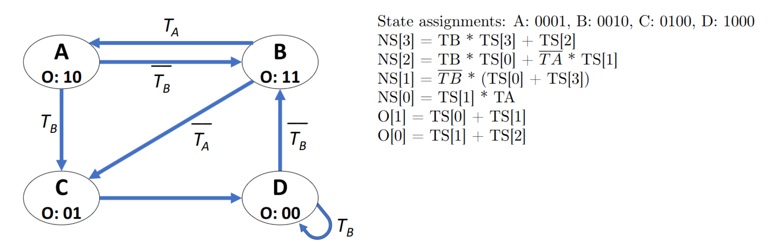
Describe FSM with One-Hot in Equations
With One-Hot you can just describe for each state (as each is one bit) which other states dependent on which signals transition to it.
Divisibility FSM
For FSM that takes bits MSB→LSB assign each remainder a state.
Then when a new bit arrives, the new remainder .
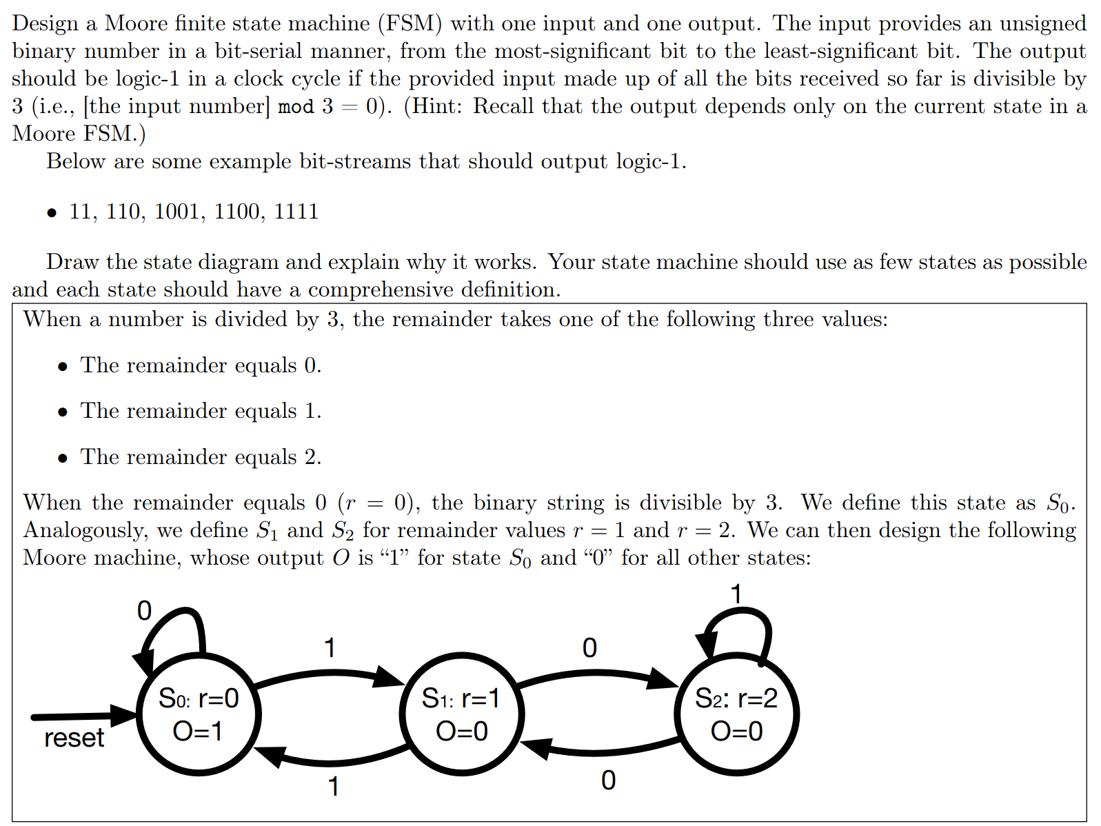
Note: this is not always the shortest way. For we can get by with only states, by knowing that a number is divisible by if the last 3 bits are .
Verilog Stuff
Verilog
active-low: (in the context of a reset for example) triggered by signal == 0
sensitivity-list: the list of inputs upon which an always @ (...) block fires
When is something sequential vs. combinational logic in Verilog?
- combinational:
- either no registers are used
- or the outputs are specified for all possible inputs
⇒ outputs depend solely on inputs
- sequenial: registers and state is held across multiple cycles
⇒ outputs depends not only on inputs (but also on previous state or something similar)
Verilog Syntax
module example (clk, a) start
	wire clk;
	reg [10:0] a = 10;
endmodule
is legal syntax → you can declare types and default values outside the module type signature declaration.
You cannot! assign twice → if wire clk was specified at the top, we cannoot redeclare.
Wire/Reg assignment: No assign of a reg!
You can also assign multiple inputs with the same wire [1:0] for example:
module top(input [1:0] in1, in2);is valid syntax.
Verilog Assignment order and updates
Non-blocking assignments < = first evaluates all RHS, then updates all LHS. This means that old values are used for all computations, then all updated at once.
a <= b
b <= a
is a working swap.
Note: if there are multiple non-blocking assignments to the same variable in blocks, the last write wins. (applied in the order executed → in code)
Blocking assignments are executed in their order.
assign out = w1;
always @ (posedge clk) w1 <= w1 + 1;
here, out updates at any time (combinational logic) → it shows the updated value immediately, also during clock cycles!
Assignment inside Always
You cannot use
assigninside an always block!
What’s more:
Assign in Always
A wire cannot be assigned inside an always block → must be driven by continuous assignment.
wire a;
always @ (*) a = b; // this is a compile error
Verilog Reset block
Why do we use:
always @ (posedge clk, posedge reset) begin
	if (reset) count <= 1;
	else count <= new_count;
end
This is better than 2 different blocks, one for clk and one for reset because if both are set to 1, it’s not clear what is triggered first.
Verilog Inferred Latch
When we have an if statement without an else block → a latch is inferred (meaning old state is preserved).
always_comb begin
 if (enable) y = a; // no else!
end
y not assigned when enable = 0 so it keeps old value → infers a latch on y.
always_comb begin
    if (enable)
        y = a;
    else
        y = 1'b0;   // every path assigns y → pure combinational, no latch
end
Here the always @ * is a red herring → purely combinational logic.
Word Bank stuff
Trimmed Signal: signal (or some bits) that don’t contribute anything (nothing observable depends on them) so are optimised away.
Multiple Drivers: For example, this has multiple drivers on q:
always @(*) q = a;
always @(*) q = b;   // q now driven by two blocks → contention
Prefix Operator
Verilog has prefix ops that apply as a reduction:
&,|,^, etc… (~&for nand,~|for nor)
So&001=0,|001=1.
Note: &&, || also exists, but it’s only as a binary loogical operator. They coerce each operand to a single truth value (nonzero ⇒ 1) and return 1 bit.
Verilog Bit Ordering
reg [7:0] a;   // descending: bit 7 is MSB, bit 0 is LSB
reg [0:7] b;   // ascending:  bit 0 is MSB, bit 7 is LSB
Adressing
Big vs. Little Endian
Order in which bytes within a word are transmitted:
- Big Endian (BE): MSB at smallest memory address
- big at the front
- Little Endian (LE): MSB at biggest memory address
- or in other words → LSB at smallest memory address
ISA vs. uarch
The compiler does not need to know about the uarch to compile a program correctly.
condition codes: Z zero flag, N (or S for sign) negative flat, V for (overflow), C for carry
number of general purpose registers: → ISA
ISA:
- memory-mapped location of exception-vectors
- Memory Model
- function of bits in programmable branch-predictor
- load/store order in Multi-core CPU
- memory consistency model
- PC width
- determines addressable space and encoding of jump targets
- memory-mapped location of exception vectors
- OS must place handlers at addresses the hardware will actually jump to!
- hard contract → change will break existing kernels
- arch defines hardware page-table walker format
- OS has to build those tables
- register windows
- layout of page table entry
- hardware walkers must agree
- big vs. small endian
- prefetching hint
- number of bits for indexing source register of a store
uarch:
- pipeline stages in cpu
- physical memory page size
- single vs. multi-cycle
Performance Evaluation
CPI
CPI: cycles per instruction
To calculate the avg. CPI (of a processor / application pair), just sum together counts (as %) * latencies.
Clock Cycle Time
clock_cycle_time = 1/ clock_freq
Execution time of an instruction
CPI * clock_cycle_time
Execution time of a program
# instr * CPI * clock_cycle_time
extra hardware choice:
- either calculate new CPIs and compare
- or use Amdahl:
- we know of instruction types
- and the multiplier / how much faster it goes
Example: Amdahl. 10% branch (4x faster), 40% memory (2x faster)
- speedup_branch = 1 / ((1 - f) + f/P) = 1/ ((1- 0.1) + 0.1/) = 1.08
- speedup_mem = 1/ ((1-f) + f/p) = 1 / ((1 - 0.4) + 0.4/2) = 1.25
Pipelining
In a MIPS pipeline there are 5 stages:
- Fetch: fetch the instruction from memory (@ PC)
- ID (instruction decode): decodes the instruction and reads register file
- where registers are read for things like
addand passed to the Ex stage
- where registers are read for things like
- EX (execute): where the ALU does it’s thing
- for memory (like
lworsw) this is where relative addresses are transformed to actual addresses - hardware interlocking stalls here when values aren’t read
- to wait on forwarding from MEM
- for memory (like
- MEM (memory): where data memory is accesses
- this is where
lwandswdo their main work (i.e. accessing main memory)
- this is where
- WB (write-back): write-back to register file
swandbnedo nothing here for example
Forwarding
In some uarch, forwarding is implemented. Examples
WB→ID: (3 apart)- this is called internal / register forwarding
- write in the first half of the cycle, read in the second half
- the values are read from register during ID phase, then given to the EX.
- Not that
WandEXin the same cycle passing data still needs explicit WB → EX data forwarding, not just the write/read separation in different halves of the clock cycle - This is just WB → ID as in ID the values are actually read.
- this is called internal / register forwarding
EX/MEM→EX orMEM/WB→EX:- 2 or 1 apart
- 2 = MEM → EX (data)
- value is read from
MEM/WBregister (i.e. the one between those stages)
- value is read from
- 1 = EX → EX (data)
- values is read from
EX/MEMregister.
- values is read from
- 2 = MEM → EX (data)
- data is forwarded to the EX inputs.
- So when
add $3, $4, $5is in EX and a previous instruction just wrote to$4(now in MEM phase), it’s forwarded and replaces the value read during ID.- this is called data forwarding (output data straight to next instr)
- 2 or 1 apart
there is also:
- MEM→MEM for
lwthensw - EX→ condition register forwarding.
Example EX forwarding.
add  $3, $1, $2    F1 D2 E3 M4 W5
sub  $5, $3, $4       F2 D3 E4 M5 W6
                            ↑ needs $3 in cycle 4
Straight from add EX phase to the sub EX phase, overwriting the value read during ID.
Note: interlocking only fires (adds bubbles) when forwarding itself is not enough to resolve the conflicts.
MIPS instruction size
MIPS ISA instruction size is 4 bytes.
Note, we do not count labels as size (assembler only, overwritten with actual offsets).
Calculating total cycle count: (Draw the pipeline here for easier counting)
- for a 5 instruction program
- latency is 5 cycles
- the final instruction will retire after 4 more.
- = total cycle count 5 * 25 + 4 final ones
Latency
When asked about the latency of the ALU (not the total latency), just count the EXECUTE stages!
Pipeline Reverse Engineering
Minimum number of register file read/write ports? We need to know how many ports each instruction type reads at the same time. Then find a cycle with a combination that does the most overlap at the same time.
- also if W and D at the same time → separate write and read port.
For a processor with instruction type INSTR, DEST, SRC1, SRC2
- in decode we read at least 2 at the same time:
SRC1, SRC2(INSTR comes from PC not from register file). - Writeback needs 1 write as there’s only 1 destination register per instruction.
Example: In cycle 8 Decode and writeback happen at the same time.
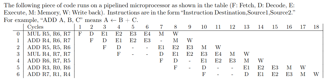
Forwarding? Find the cycles in which hazards are bypassed from M→E or WB→ID directly.
→ make sure to differentiate register vs. data forwarding.
hardware vs. software interlocking? who is responsible for stalling when instructions are interdependent, compiler or processor?
- hardware: bubbles are inserted to stall (instructions not reordered)
- software: nops or reordering to prevent interdependence.
→ note, when inserting NOPs into the code when simulating software interlocking, the NOPs still go through the pipline (insert the F, D, E1, E2…)
Dynamic vs. static instruction
Static instruction = an instruction as it exists in the program binary → one slot in memory.
Dynamic instruction = one execution of an instruction at runtime.
Note: this matters because of branching. The dynamic count could be 100 or 0 (if we never branch).
Pipeline bubbles propagate
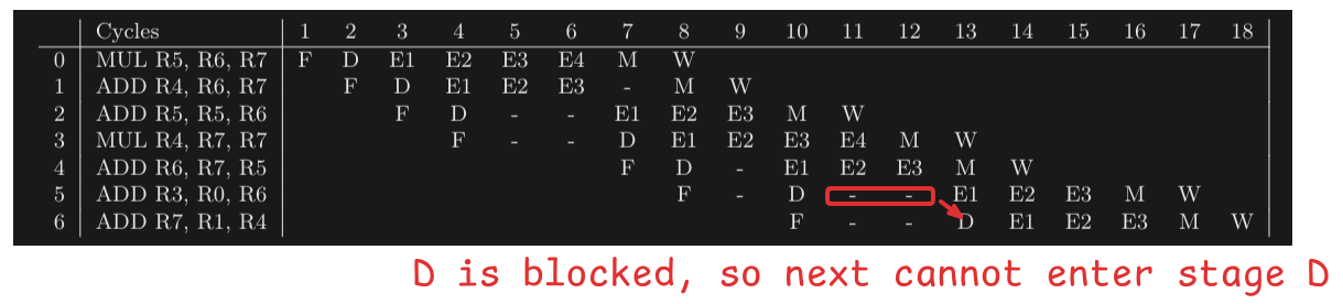
We cannot take an instruction “out of the pipeline” - aufs Abstellgleis. If something blocks the pipeline, all other instructions are also stalled.
No overtaking!
Example:
F  D  -  -  - E1 E2 E3 M W
   F  D  E1 E2 <- impossible, no overtaking!
or
Writebacks in PO
Due to there not being overtaking, writebacks also happen in program order!
Why does D take 1 or 2 cycles? we might only have 1 read port.
- Immediate instructions → need only 1
- forwarded-instructions → need only 1 too
- all others → need 2 for two operands!
Pipeline length or Cycles Taken
Pipeline Equation
The Formula for cycles taken is where
- means number of cycles
- means number of pipeline stages
- means number of (dynamic) instructions
- means number of conditional branches taken/number of conditional branch instructions executed
- means number of cycles stalled for each conditional branch
Tomasulo’s
number of tag comparators per reservation station entry: source registers (per reservation station entry) * data buses
→ it needs one comparator for each data bus!
total number of tag comparators: functional units * reservation station entries (per fu) * source registers * data buses + RAT entries * data buses
→ don’t forget the RAT also has a comparator per entry per data bus
total tag storage: RAT + reservation stations
Seperate Output bus: both adder and multiplier have to have a separate data-bus in order to be able to retire both at the same time (write to RAT at the same time).
Out-Of-Order: Because this uses Out-of-Order → on stall no need to wait. We can fetch + decode as many as we want!
Tomasulo Reverse Engineering
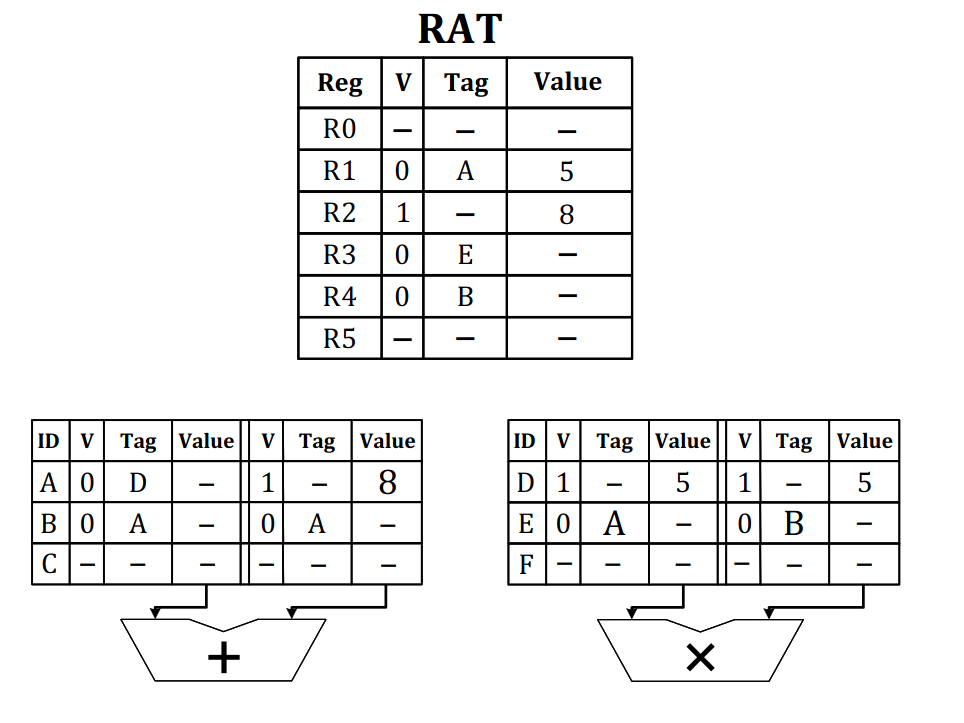
D was the first instruction → both it’s source registers are valid.
- Because A reads D, D writes into
R1as well and was overwritten. - so
mul r1, r1, r1was the first instruction
A reads 8 as a value in one of the source registers.
- that can only have been
r2.
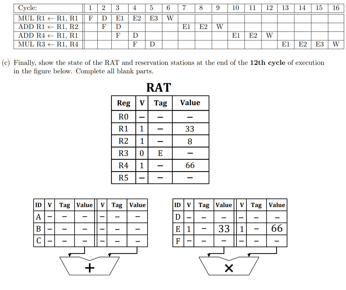
Once an instruction has successfully WB → it’s tag is deleted from the RAT and replaced with V=1 and the value. The reservation station is then cleared.
Tomasulo DataFlow
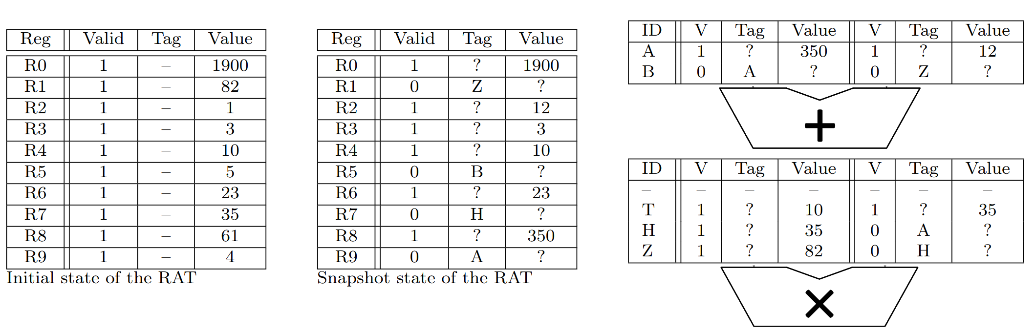
Recover this Dataflow graph from the RS and RAT. See which data is in the original Registers, see what could be computed together to give the right values. Then match them up.
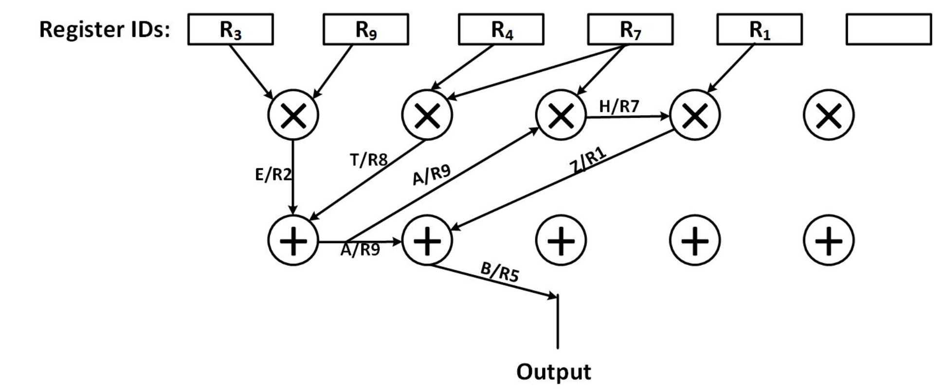
To recompute the program from that, use topological order to sort them.
Tomasulo Program, RAT and RS reversing
Pay attention to the RAT → value bits are only overwritten when the instruction actually completes.
So if we have R0 1 - 10 and then add with tag A has R0 as dest, it becomes: R0 0 A 10 (the 10 stays, the data is only overwritten once add completes).
Branch Prediction
When asked to fill out a table to get 100% miss rate for ex, remember the lead-in!
Lead-In
There is always a NN lead-in to take into account.
This makes sure we have something to index the first branch with.
Example: We have sequence TTT…NT, so prepend the NN lead in. Then we have NN → T, NT → T, etc…
Calculate stall cycles: Cycles = pipeline_stages + dynamic_instructions - 1 + conditional_branches * stall_cycles
then find and solve the equation.
Accuracy for finite loop → no need to separately count the first / last instructions, etc… for ifs (only for for loops), give rate instead of exact.876
VLIW
Motivation fo VLIW: Allow for multiple instruction issue with simple hardware. Independent instructions can be scheduled into a single VLIW instructions without the need for hardware interlocking or more complex pipelining.
Note: Instructions that Write/Read the same registers can be scheduled in the same VLIW instruction!
- the registers are read in the first half of the cycle
- then they are written in the second half → no interference.
Example:ADDI r1, r1, 4 | LD f1, 0 (r1) | NOPeven though the add overwritesr1, the fetch still works correctly.
Latency READ VERY CAREFULLY!
- if nothing is written
- if there’s an instr with latency 1 = +1 whole cycle per latency
- otherwise it means latency count with the instructions issue cycle already counted. So FPU latency = 3 means that after 2 NOPs the data is ready and the unit is free again.
- if anything is written → follow that, e.g. “Latency 1 means available next cycle”…
Def Unrolling once → make each iteration of the loop do the work of 2, i.e. append two iterations after each other directly.
Example: Here two iterations are packed into one, and interleaved with each other. The first is using f1, f2, the second f3, f4 independently.
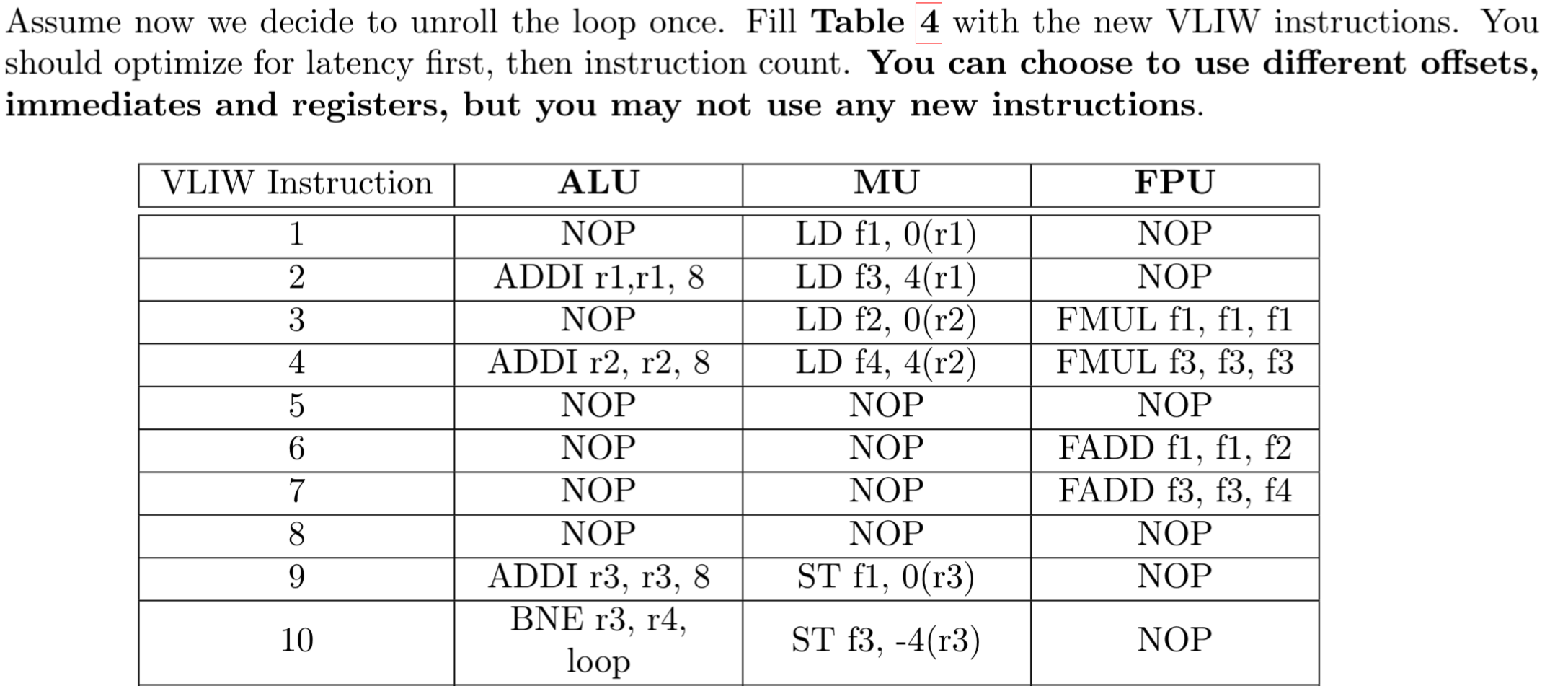
Maximum instructions / cycle: unroll the loop to times, checking how close you can pack everything. Then add together the instructions and divide by the number of cycles it takes in total.
→ unrolling should probably be less than 5-fold for reasonable exercise.
Width of the VLIW instructions (from Dataflow Graph). Go through and count the number of VLIW instructions it would take
- only packing together instructions on the same layer of the dataflow graph
- as those must be independent.
Minimum to get maximum performance: The width of the dataflow graph at it’s widest section.
Comparison to in-order superscalar:
- slower → VLIW reorders, “in-order” superscalar must insert bubbles
- faster → instruction density is higher in superscalar if there are no dependencies, VLIW must insert the NOPs.
Cache Reverse Engineering
Keep in mind to always convert from address to block!!! Otherwise everything else will be wrong.
Find sets/ways knowing the block size and blocks
Here, you just convert address → block and then for each possible set/way combination, draw the final state of the cache (ideally in their block representation).
Then, figure out a combination that gives distinct access patterns.
Choose the lowest addresses → for each address you chose in your sequence, find the lowest address in the block!
- for with block size 4,
- convert to .