An FSM diagram visually depicts:
- All possible states: The set of all distinct configurations the system can be in.
- State transitions: How the system moves from one state to another based on inputs and current state.
4.1 Mealy vs. Moore
There are two type machines:
- Moore
- outputs are tied to states (each output is associated to a state)
- state transitions are the inputs (inputs cause state transitions, labelled with those inputs)
- each state needs defined output!
- “outputs depend on current state only”
- Mealy:
- outputs are tied to state transitions
- “outputs depend on current state and inputs”
→ differences: outputs & state transitions
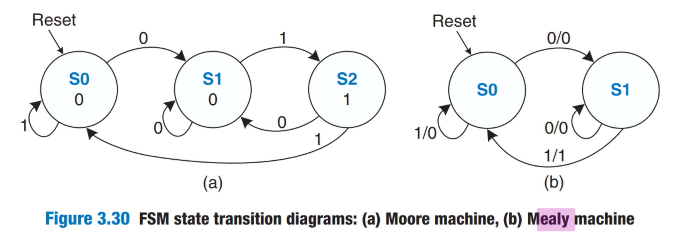
Conversion: Moore → Mealy, Mealy → Moore
- We can always convert between them
Reset Arrow
Both FSMs have a reset transition → arrow labelled “Reset” going into the default state.
All Outputs / Inputs
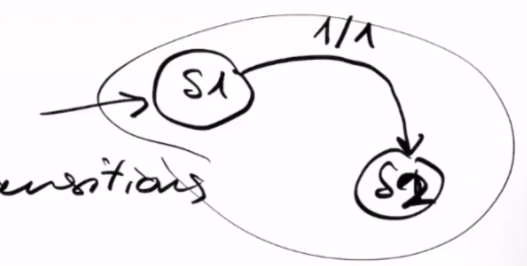
All states must have transitions for all inputs (otherwise illegal).
Example: This is illegal, we need a transition for 0 input
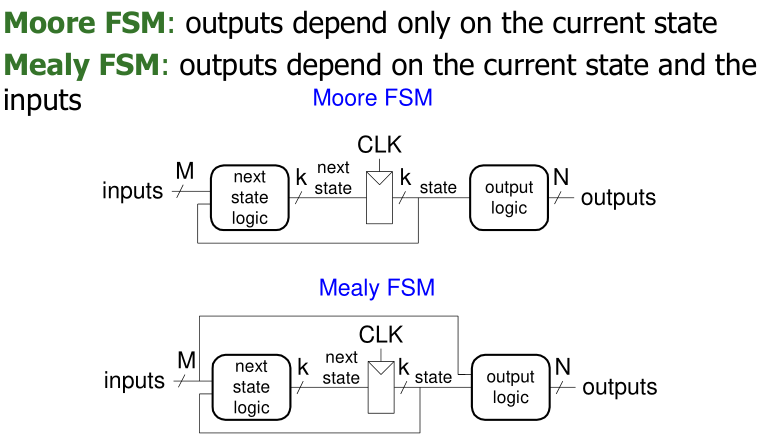
In hardware:
Combinational Circuits:
- Next State Logic: Determines the
next statebased on thecurrent stateand inputs. - Output Logic: Generates the
outputsbased on thecurrent state(Moore) orcurrent stateand inputs (Mealy).
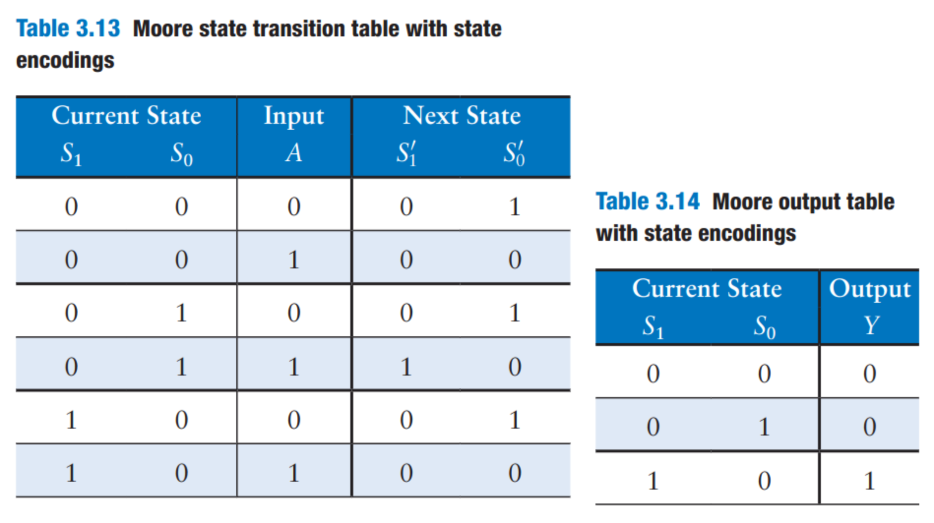
4.1.1 Moore
4.1.2 Mealy
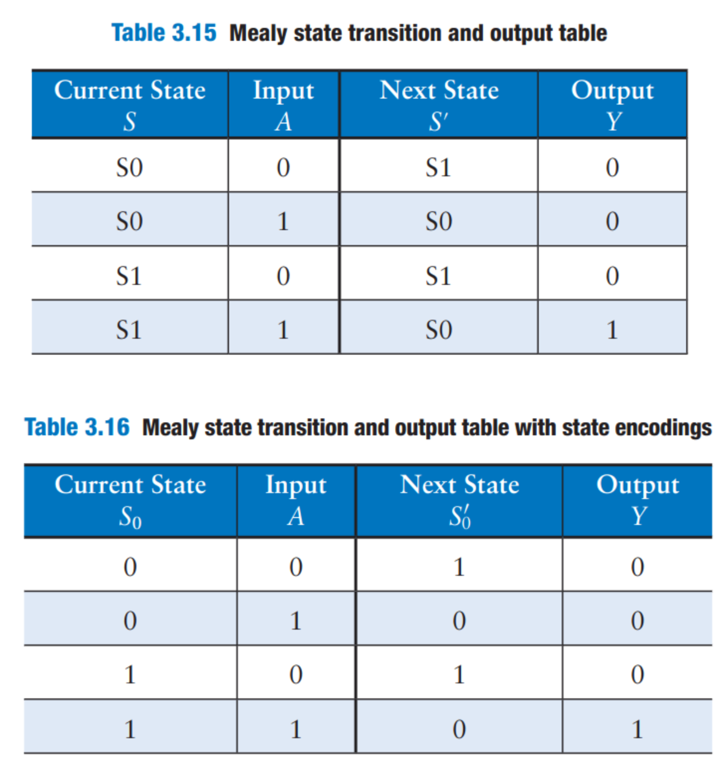
4.2 State transition Factoring
We can simplify state transition diagrams using factoring. This means “grouping” them by functionality and then having interacting state transition arrows:
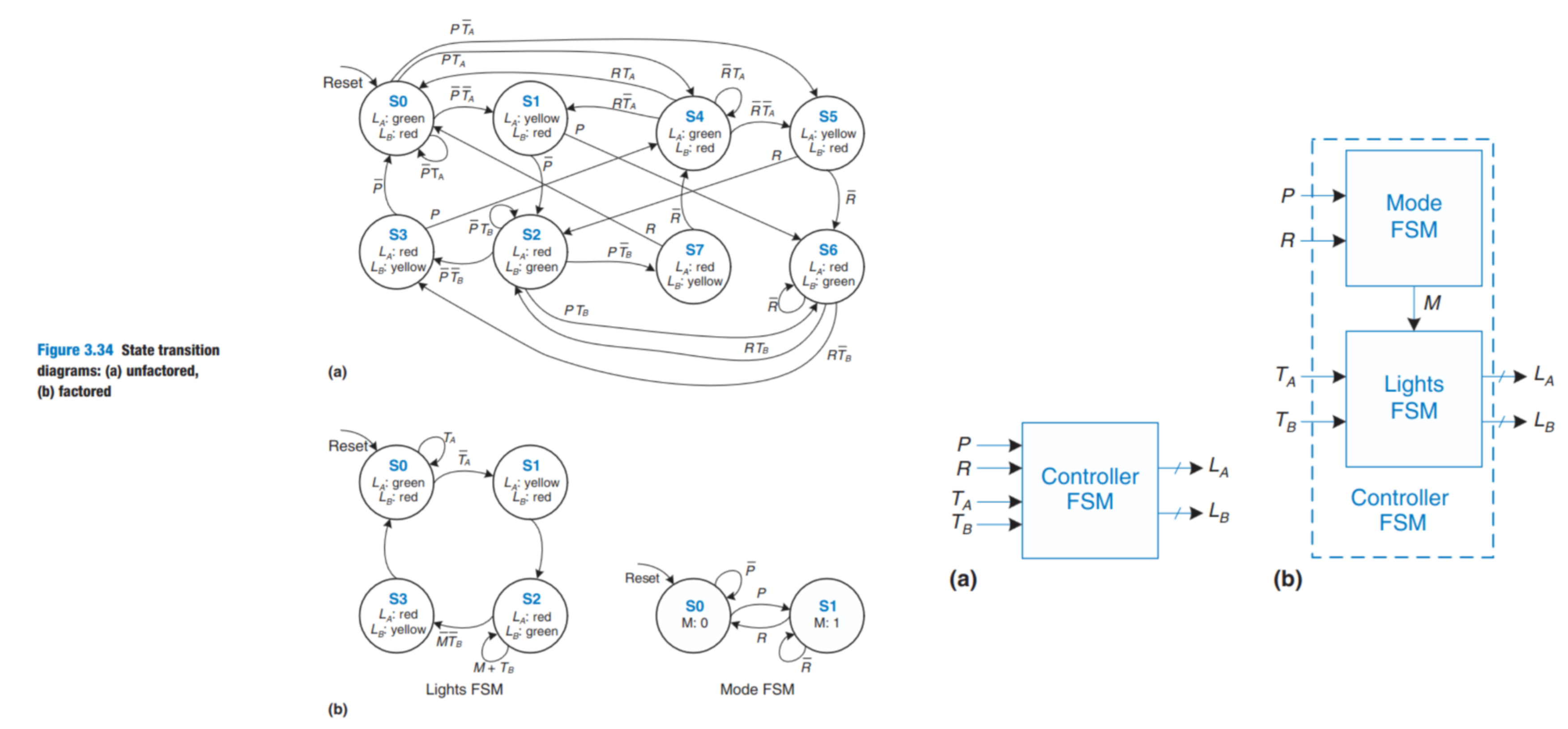
→ Output of some machines is the input of others!
4.3 Simplifying FSMs
Exam Relevant
We transform the state machine into a truth table (state / input, output, next-state). From this, we can read off two possible simplifications:
- unreachable state (not in next-state of any state)
- mergeable (exactly same input/output/next-state)
(from problem solving session)
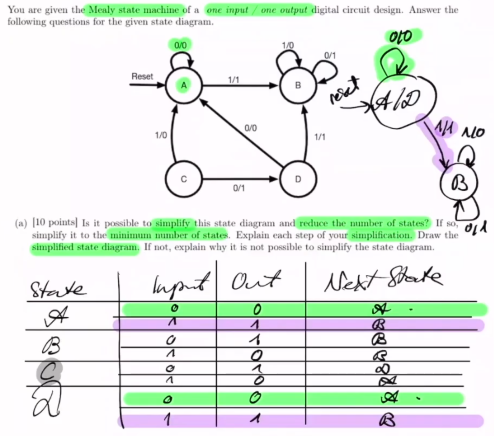
- We can see A and D both have the exact same table
- C is not reachable from any state
thus we merge A, D (keep all input arrows!)
and remove C
Note: This doesn’t mean the simplification is done!
- keep the truth table and update it:
- might have cascading updates.
FSM State Encodings
We can use:
- One-hot encoding (i.e. one bit enabled, so n-bits wide state vector)
- Binary encoding (dense)
- Output encoding → state vector = output
Advantages:
- One-Hot:
- reduces next-state logic
- Binary
- reduces Flip-Flops to hold state
- Output:
- reduces output logic
Exam Tipps:
Checklist for FSM Exercises:
- Reset ?
- 1/0 (or all possible transitions) output for each state?